Debugging a 1-Bit Adder
17 Feb 2025
I’m working on building an 8-bit adder using transistors. While soldering together this 1 bit adder I made a mistake and had to debug it to figure out where the error was. Here’s how I did it.
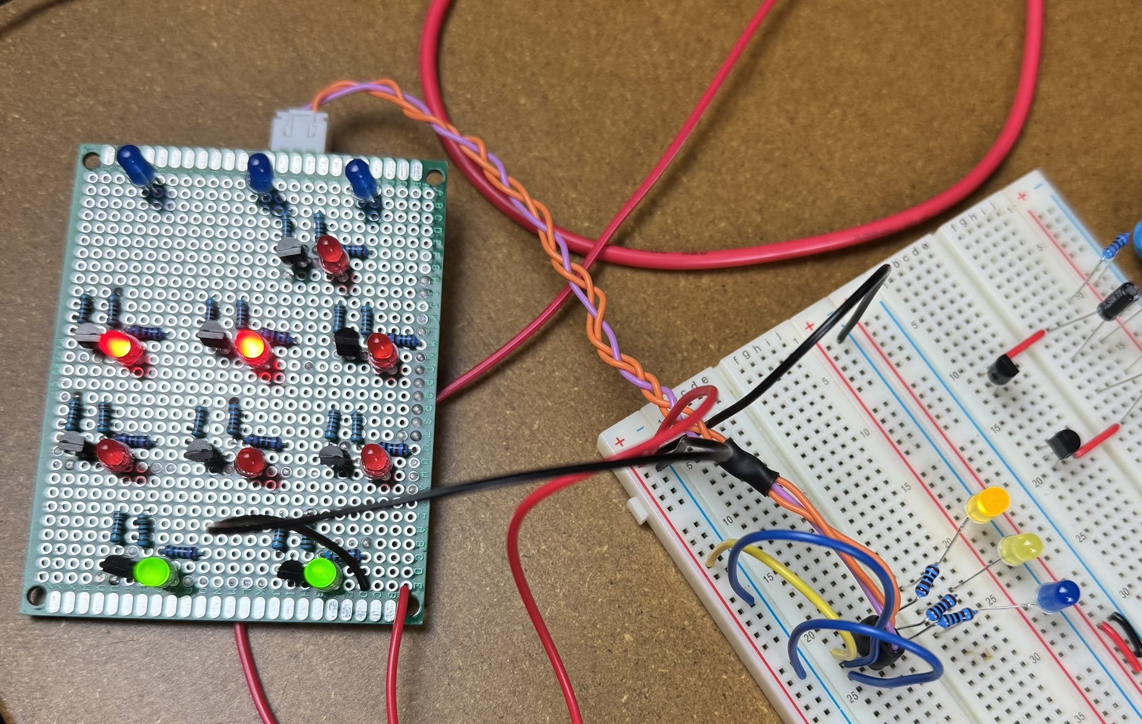
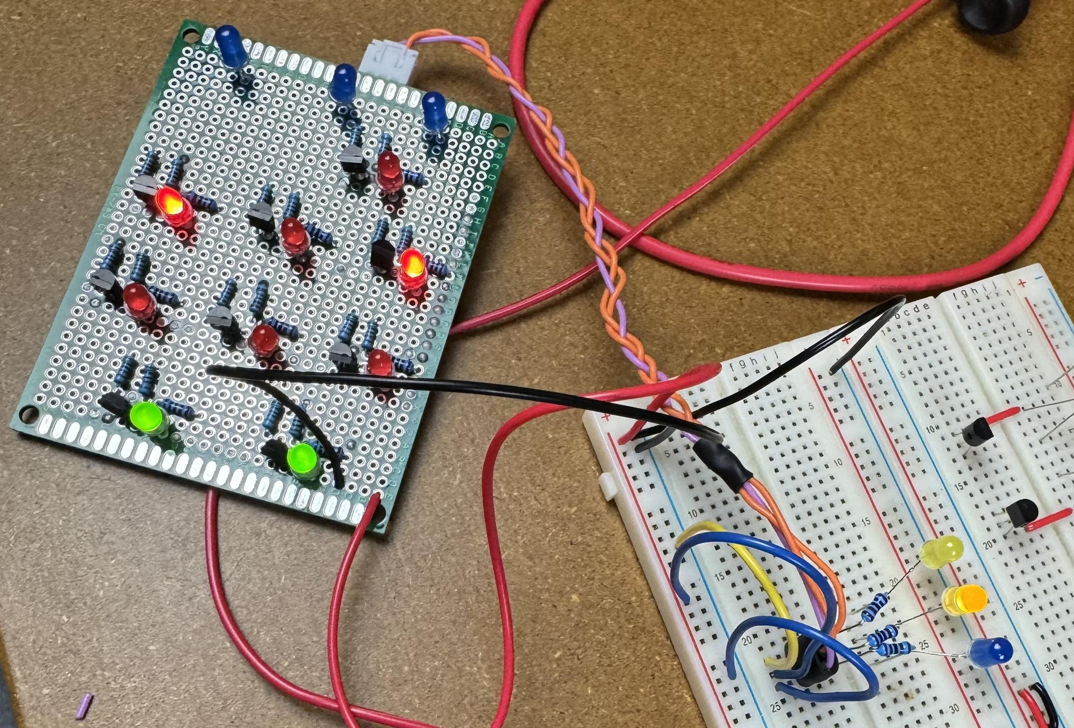
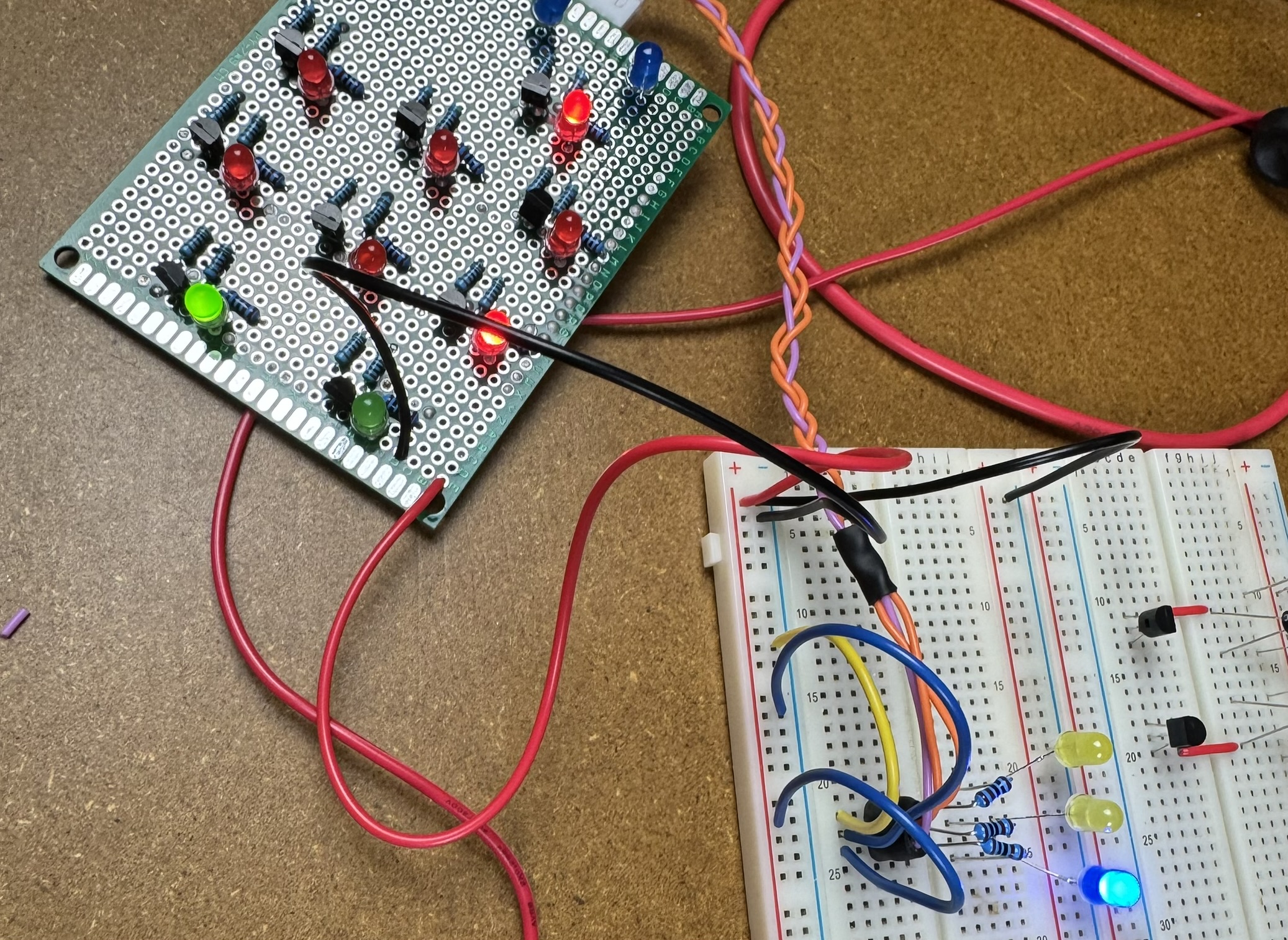
Testing
When testing the board I immediately realized I had made a mistake, because it did not produce the expected output.
1-bit adder truth table:
| A | B | Cin | Sum | Cout |
|---|---|---|---|---|
| 0 | 0 | 0 | 0 | 0 |
| 0 | 0 | 1 | 1 | 0 |
| 0 | 1 | 0 | 1 | 0 |
| 0 | 1 | 1 | 0 | 1 |
| 1 | 0 | 0 | 1 | 0 |
| 1 | 0 | 1 | 0 | 1 |
| 1 | 1 | 0 | 0 | 1 |
| 1 | 1 | 1 | 1 | 1 |
Expected:
| A | B | Cin | Sum | Cout |
|---|---|---|---|---|
| 1 | 0 | 0 | 1 | 0 |
Actual:
| A | B | Cin | Sum | Cout |
|---|---|---|---|---|
| 1 | 0 | 0 | 1 | 1 |
Inputs: A=0, B=1, C_in=0 Expected output: Sum=1, C_out=0 Actual output: Sum=1, C_out=1
Expected:
| A | B | Cin | Sum | Cout |
|---|---|---|---|---|
| 0 | 1 | 0 | 1 | 0 |
Actual:
| A | B | Cin | Sum | Cout |
|---|---|---|---|---|
| 0 | 1 | 0 | 1 | 1 |
The Carry-in input (C_in) resulted in the correct output.
| A | B | Cin | Sum | Cout |
|---|---|---|---|---|
| 0 | 0 | 1 | 1 | 0 |
Comparing to the simulator The next step was to compare these results with the circuit I had build in Logisim. Here’s a screenshot of the same circuit (at the logic gate level) in Logisim:
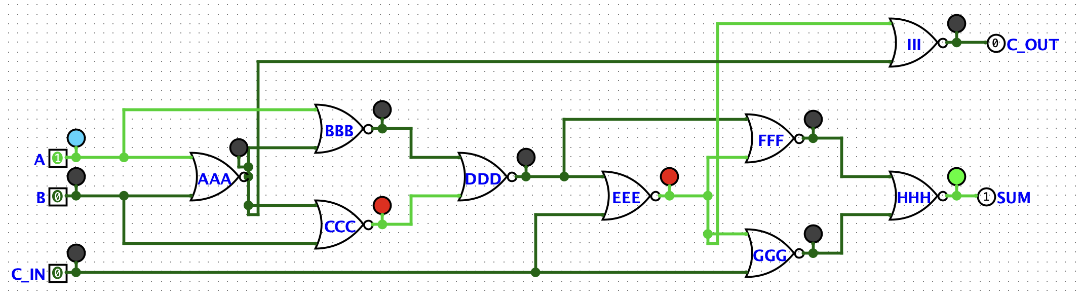
Here’s the circuit with the gates labelled to match the simulator:
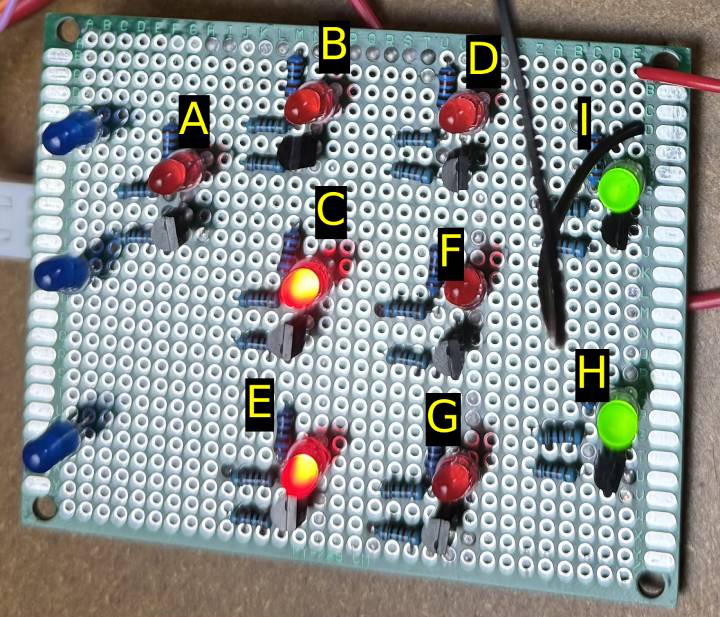
By comparing the state of each gate, we can see that only the I (Sum) gate is incorrect, so it was likely that one of the inputs to that gate was soldering incorrectly. Looking at the inputs to the I (labelled III in Logisim) and considering the truth table for a NOR gate, the only way for that gate to be ON is when both inputs are OFF.
NOR gate truth table:
| A | B | OUT |
|---|---|---|
| 0 | 0 | 1 |
| 0 | 1 | 0 |
| 1 | 0 | 0 |
| 1 | 1 | 0 |
We expect the top input of that gate to be connected to the output of the E gate, which is correctly ON in this state, so it is a safe guess that the connection between the output of the E gate and that input to the I gate to be soldering incorrectly.
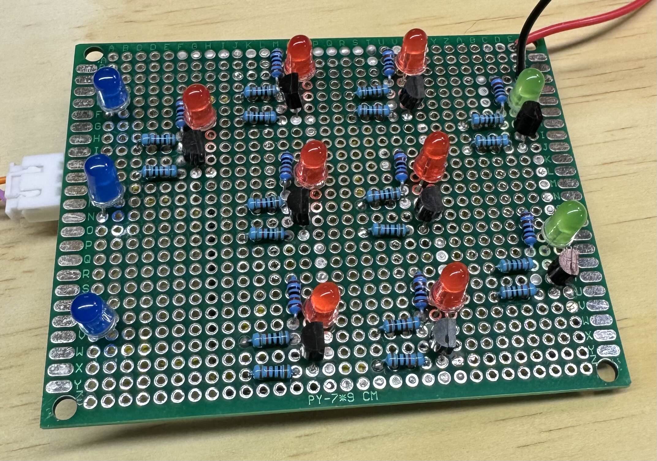
That turned out to be correct and here is the underside of the completed circuit:
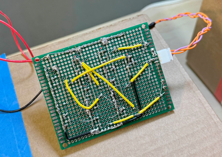
Now I just need to make 7 more…